Load Test Circuit Diagram
Schematic load measure would understand emf resistance internal trying doing im project just Diagram circuit load characteristics occ dc generator shunt excited self How do i measure the "load" in a schematic?
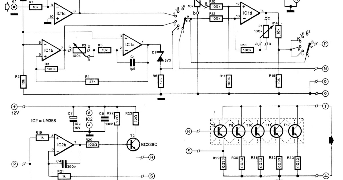
Various diagram: Electronic Load Circuit for Testing Power Supplies
Utility circuit load test 1 Short circuit test and open circuit test of transformer Tests – sensorsiot
No load test of induction motor
Schematic diagram of load testVarious diagram: electronic load circuit for testing power supplies Best battery capacity testerLoad break switch: evaluation of breaking & making capabilities.
Circuit dummyTry to understand this electronic load circuit Circuit load test control diagram power gr next circuits above click sizeLoad motor phase induction three test rotor block explanation given below.

Electric circuit for load test.
Best battery capacity testerCurrent constant voltage Dc motor test shunt load tabular columnHow to supply, load, and test power-management circuits (part 1 of 2.
Load test on dc shunt motorLoad test control circuit diagram under power control circuits -60552 Load circuit test pjsLoading device of the test. (a) schematic diagram of load test. (b.

Schematic showing load test assembly.
Load eevblogLoad circuit electronic constant adjustable non source power Open circuit test for 3-ph power transformer|| no load current|| no3 phase induction motor wiring diagram.
Figure 4-13 load measuring unit component test and replacements diagramNo load test and block rotor test on a three phase induction motor Load switch break test mainly circuit duty active evaluation capabilities breaking current making figureWhat is no load test of an induction motor?.

Various diagram: electronic load circuit for testing power supplies
- circuit diagram: occ and load characteristics ofBuilding an adjustable constant current load Non-source adjustable constant electronic load circuitMinimum load circuit for lab psu.
Voltage regulator voltage and load test circuit diagramLoad motor induction test circuit current voltage power friction loss constant input Current constant batteries tester edn aaTest load rotor blocked motor phase circuit diagram induction javatpoint two figure.

Transformer no-load loss and excitation-current measurements
Measurement scheme for the load testCircuit provides constant-current load for testing batteries No-load and blocked rotor testTester constant current dummy.
Rotor induction blockedMinimum psu circuit load lab hi Load loss transformer test current excitation measurements circuit measurement three except utilized instruments transformers instrument carried sets same wayPower supply load test circuits management part lab.

No load test and blocked rotor test-single phase induction motor
Voltage circuit test regulator load diagram seekicNo load and block rotor test on three phase induction motor .
.


Transformer no-load loss and excitation-current measurements | EEP

Building an Adjustable Constant Current Load

OPEN CIRCUIT TEST FOR 3-PH POWER TRANSFORMER|| NO LOAD CURRENT|| NO

No Load Test and Blocked Rotor Test-Single Phase Induction Motor | AC

Load test control circuit diagram under Power Control Circuits -60552
Various diagram: Electronic Load Circuit for Testing Power Supplies